Helix World +
Theory of electric and magnetic field in electromagnetic waves
1 Electromagnetic waves have no electric field − 日本語 − Reference王様は裸
2 Unclear about radio waves − 日本語 −
3 Form of current − 日本語 −
4 Electrical and Magnetic forces − 日本語 −
5 Electromagnetic waves are traveling magnetic fields − 日本語 −
6 Generate electromagnetic waves − 日本語 −
7 Receive electromagnetic waves − 日本語 −
8 Polarization − 日本語 −
9 Insertion device for synchrotron − 日本語 −
10 Longitudinal and Transverse Waves − 日本語 −
Sept./05/2023
< 1 Dipole antenna to receive magnetic field >
As shown in Figure 1, when an approaching (traveling) alternating magnetic field (radio wave) crosses a rod antenna or dipole antenna, which is a rod-shaped (wire-shaped) conductor, an electromotive force is produced a current in the antenna, and the current corresponding to the traveling magnetic field is output from the output section.
In the figure, orange indicates the magnetic field in the direction from the front to the back of the screen, and blue indicates the magnetic field in the direction from the back to the front of the screen, and the same color scheme is used below to indicate the direction of the magnetic field.
![]()
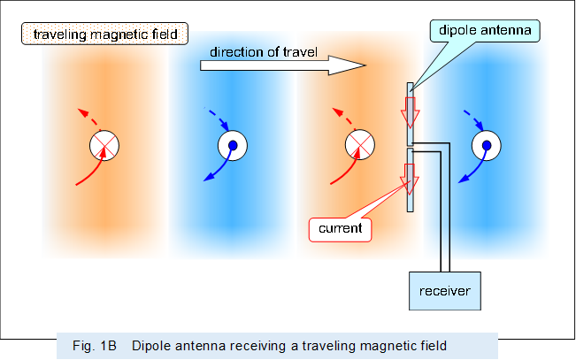 |
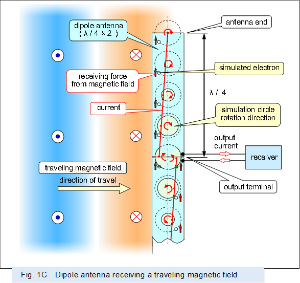
Figure 1C shows how the approaching (traveling) magnetic field vibrates the electrons in the antenna when it crosses the dipole antenna, producing a current, using the simulated circle described in "Form of current".
The simulated circle and simulated electron shown by the dashed lines show how each electron in the antenna vibrates in phase when a force of the same magnitude is exerted on each electron at the same timing due to the Lorentz force produced by the magnetic field that is approaching.
The vibration of the electron at each location vibrating in phase is added to the vibration of the neighboring electron, and the vibration of the electron at each location increases sequentially, as shown by the solid simulated circle enlarging sequentially.
Then, the current produced by the electron with increased vibration is output.
 |
As described above, all electrons in the antenna vibrate in-phase as they are driven by the traveling magnetic field (alternating magnetic field).
The electrons vibrating in-phase are the same as those in the half-cycle of the standing wave shown in "Form of current".
Therefore, if the length of the antenna is long enough to form a standing wave, all the driven electrons will form a single wave and the vibration amplitude of the electrons at each location can be increased.
In other words, if the length of the antenna is long enough to form a standing wave, the traveling magnetic field can be converted into a current with high efficiency and a big current can be output.
Note that it has been thought that "radio waves have an electric field, which produces a potential difference between the two ends of a bar antenna, and a current is output according to that potential difference," but as described above, a similar current is output by a traveling magnetic field (an alternating magnetic field).
In other words, even if a rod-shaped antenna receives a radio wave and outputs a current, it cannot claim that the radio wave has an electric field.
< 2 Loop antenna to receive magnetic field >
When an approaching (traveling) alternating magnetic field (radio wave) crosses a loop antenna composed of conductors, an electromotive force is produced a current in the antenna, and the current corresponding to the traveling magnetic field is output from the output section.
As shown in Figure 2, in a loop antenna which diameter is about 1/2 wavelength of the received alternating magnetic field, the semicircle on the output side operates like the above dipole antenna and outputs a current.
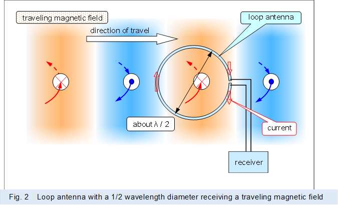 |
In the above loop antenna with a 1/2 wavelength diameter, the semicircle on the opposite side of the output side also produces a current like a dipole antenna and operates like a waveguide for the alternating magnetic field to be received, because this opposite side semicircle is about 1/2 wavelength away from the output side.
Thus, the 1/2 wavelength loop antenna has the characteristics of a Yagi-Uda antenna with a single waveguide.
As shown in Figure 3, in a loop antenna which diameter is smaller than 1/2 wavelength of the alternating magnetic field to be received, this antenna operates like a coil through which the alternating magnetic field penetrates, because each part of the loop is received a magnetic field of the same phase.
In other words, in a loop antenna which diameter is smaller than 1/2 wavelength of the alternating magnetic field, a current is output that against changes in the penetrating magnetic field by electromagnetic induction operation or magnetic resonance operation, like a coil.
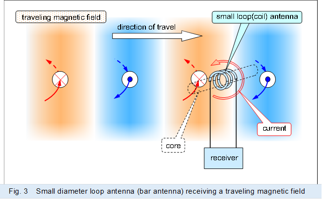 |
When the aperture is small relative to the wavelength of the alternating magnetic field to be received, as in the loop or coil in Figure 3, the magnetic field that penetrates is small and a big output cannot be produced. In many cases, the aperture area is made as large as possible, as in the spider coil or basket coil, where the conductor is wound around multiple times for exclusive receiver use.
In addition, in many cases, a core that collects the magnetic field is inserted, like a bar antenna.
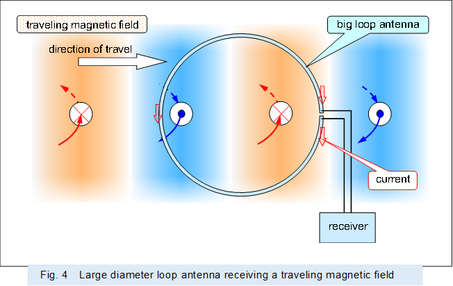
As shown in Figure 4, even in a loop antenna which diameter is larger than 1/2 wavelength of the received alternating magnetic field, the semicircle on the output side operates like a dipole antenna and outputs a current.
However, it receives magnetic fields other than the semicircle on the output side, and the current produced there is not resonant as in the 1/2 wavelength loop antenna above, which inhibits the production of output current and cannot output sufficient current.
 |
Incidentally, the ring-shaped conductor that Dr. Hertz used to prove the existence of radio waves is small relative to the wavelength of the transmitted radio waves, and should be considered a receiving coil rather than a loop antenna.
Thus, as above, even if a ring-shaped conductor receives a radio waves, it cannot claim that the radio waves are formed by an electric field.
< 3 Effect of magnetic field >
As shown in Figure 5, when a metal plate (conductor) is placed in a traveling magnetic field (alternating magnetic field), the magnetic field pushes the metal plate in the direction the magnetic field is traveling. Because eddy currents are produced in the metal plate to obstruct changes in the magnetic field and Lorentz force is produced between the eddy currents and the magnetic field.
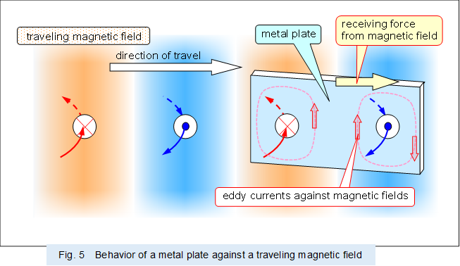 |
The above behavior is the same as that of an AC motor which rotates a rotor or a linear motor which moves in a straight line.
As shown in Figure 6, when an object with a polarized part is placed in a traveling magnetic field (alternating magnetic field), the polarized part to vibrate in each direction. Because the Lorentz force due to the traveling magnetic field actuates the part polarized to a positive or negative potential.
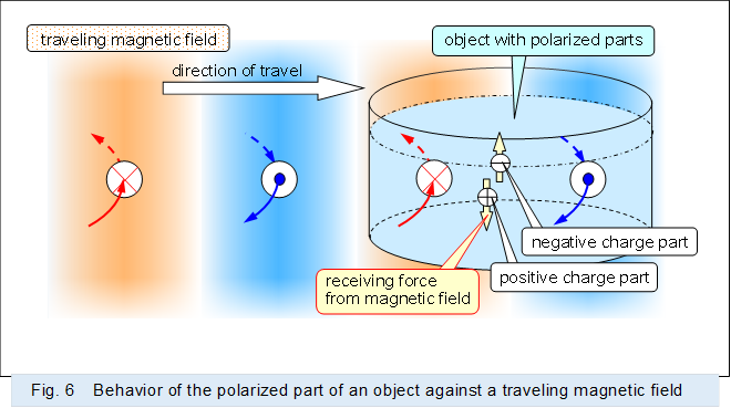 |
For reference, an ordinary microwave oven use a radio wave (traveling magnetic field) at 2.45 GHz to vibrate the water molecules and heat the water.
As described above, electromagnetic waves (traveling magnetic fields) including radio waves and light have kinetic energy even if they have no mass. Because magnetic fields traveling at the speed of light exert a force on objects.
And what replaces mass in electromagnetic waves (traveling magnetic fields), including radio waves and light, is the intensity of the magnetic field.